1
Mechanical System Parameter

| Remark |
|---|
| 2 Cooling Mashines on Rough |
| 2 DX Cooling Systems per Cube – 2 × 150 kW |
| 5 Water Cooling Systems per Cube – 5 × 110 kW |
| 3 Water Pumps Primary – Secondary N+1 |
| 2 External Bypass Primary – Secondary |
| < 16º Celsius – Fresh Air – >16° Water Cooling |
| > 40° Celsius – Compressed Air Cooling |
| All Air Condition Systems included in BMS |
| Leakage Sensors at each Air Condition System |
| Leakage Sensors under Water Pipes |
2
Mechanical System - Overview
| Air Flow Managemt & Ventilation | |
|---|---|
| Hot Aisle / Cold Aisle | Cold Aisle Containment |
| Raised Floor | 100 cm Raised Floor to ensure Airflow |
| Fresh Air Intake | Ventilation Flaps ensure Fresh Air Intake |
| Exhaust Systems | Ventilation Flaps remove Hot Air Intake |
| Cooling Control | 500 kW (maximum UPS Capacity 1500 kW) |
| Air Flow Managemt & Ventilation | Remark |
|---|---|
| Fire Alarm Sensors | Distributed in all Rooms |
| Fire Extinguishing | 7 Zones for Cube 1/2/3 UPS and Battery Rooms |
| Extinguishing Gas | N2 |
| External Fire Alarm | Transmitted to Local Fire Brigade |
| Fire Control | Managed by BMS System (Alarm in BMS) |
| Air Flow Managemt & Ventilation | |
|---|---|
| BMS System | 2 Server (Redundant) |
| BMS Line Controller | 2 IOT Controller (Redundant) |
| Air Condition | Modbus over tcp |
| Power Systems | Modbus over tcp / Modbus RS485 |
| Fire Control | Modbus over tcp |
| Environmental | 4-20 mA Analog Control Cable |
| Leakage | 4-20 mA Analog Control Cable |
| Air Flow Managemt & Ventilation | Remark |
|---|---|
| Racks | Category in CMDB |
| Power Nodes | Category in CMDB |
| Sensors | Category in CMDB |
| Aircon System | Category in CMDB |
| ODF / Patch Panel | Category in CMDB |
| Cameras | Category in CMDB |
| Network | IP-Nodes and DWDM Nodes Category in CMDB |
3
BMS and Monitoring

4
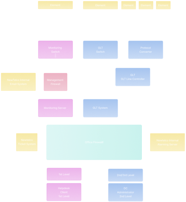
BMS (GLT) & Monitoring Functions
-
Element
- Temperature Sensors
- Leakage Sensors
- Door Sensors
- Fire Detection Controller
- Aircondition Systems
- UPS & DG / Power Switches
-
Protocol Converter
- Converts Modbus RS485
- Converts 24 V Analog Signals
- Converts 24 V Digital Signals
- 2 Converter - UPS Room 1 / 2
- 3 Converter - Cube 1 / 2 / 3
- GLT Ring
-
GLT Switch
- 5 GLT Switches in front of Converter
- 2 GLT Switches in front of GLT Servers
- GLT Network Ring - Deticated Network
-
GLT Line Controller
- Implemented in UPS Room 1/2
- Redundant Setup
- Connected to GLT Switch
- Communication towards FLT Server
-
GLT System
- Information for 2nd Level Support / DC Team
- Monitoring all BMS Elements
- 2 Server Setup
- Virtualisation via PROXMOX
- Hot standby Setup
- Frontend Server SQL Server
-
Monitoring Switch
- Connects Network Elements
- Connects IT Systems
- Interconnect to GLT Switches
- Deticated Monitoring Network
-
Management Firewall
- Seperates Network Elements from Network Servers
- Connects internal DNS / Email / NTP / FTP Servers
-
Monitoring System
- Information for 1st Level Helpdesk
- Information received via SNMP or Monitoring Agent